

Induction furnace:Structure of an induction furnace
The Structural Design and Tilting Mechanisms of Medium Frequency Induction Furnaces
1. Overview of the Induction Furnace Body Structure
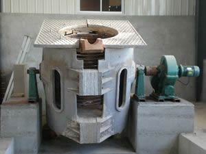
The structural form of the Medium Frequency (MF) induction furnace body is essentially the same as that of the Power Frequency (PF) induction furnace. The furnace body section is comprised of the following core components:
-
Furnace Frame: The primary supporting structure.
-
Furnace Body: Available in two types—Frame Type and Shell Type.
-
Furnace Lid: For thermal retention and safety.
-
Tilting Mechanism: For pouring molten metal.
-
Cooling Water System: To manage the thermal load on the inductor.
-
Power Supply System: The electrical input interface.
Industrial examples include the 150kg MF induction furnace and the 500kg MF induction furnace, both commonly equipped with hydraulic tilting devices for precision pouring.
2. Structural Differences: Medium Frequency (MF) vs. Power Frequency (PF)
The primary structural difference between MF and PF induction furnaces lies in the relative position of the crucible to the inductor and the cross-sectional dimensions of the inductor.
Relative Position of Liquid Metal and Inductor
In a Medium Frequency induction furnace, the liquid metal is usually completely surrounded by the inductor, with the metal level remaining lower than the top of the inductor.
In contrast, in a Power Frequency induction furnace, the metal level is higher than the inductor. This design is intended to weaken the intense electromagnetic stirring effect characteristic of power frequency operation. Because the electromagnetic force in PF furnaces is greater than in MF furnaces, the height of the liquid column must be increased to utilize gravity to counteract the “hump” effect and reduce the erosion caused by the churning molten steel.
Height Ratios ($H$ vs. $H_L$)
The relationship between the inductor height ($H$) and the liquid column height ($H_L$) is defined by the following formulas:
-
Medium Frequency Induction Furnace:
$$H \approx (1.1 \sim 1.3)H_L$$ -
Power Frequency Induction Furnace:
$$H \approx (0.8 \sim 0.9)H_L$$
Summary: The inductor in an MF furnace is typically 1–2 turns higher than the liquid metal column, whereas in a PF furnace, the liquid metal column rises 1–2 turns above the inductor.
3. Inductor Cross-Section and Design
Regarding the cross-sectional dimensions, MF inductors use thinner tubing walls. This is due to two factors:
-
Skin Effect: The skin effect intensifies as frequency increases, concentrating current on the surface.
-
Electrical Parameters: MF inductors feature high terminal voltage and relatively small oscillation circuit currents.
The structural shape and insulation treatment of MF furnace inductors remain identical to those used in Power Frequency furnaces.
4. Classification of Tilting Mechanisms
Medium Frequency induction furnaces typically have capacities under 10 tons, with the majority of units in operation being under 1 ton. There are four primary types of tilting mechanisms used for small and medium-sized furnaces:
1. Hoisting Tilting (Crane-based)
This is the most traditional method. It utilizes an overhead crane or a specialized small hoist to lift the lifting rings installed on the furnace body. This method is considered obsolete and is gradually being phased out of modern foundries.
2. Screw Drive Tilting Mechanism
This system uses an electric motor and a reducer to drive a screw-jack lifting device. This mechanism is only suitable for very small furnaces, such as the 150kg MF induction furnace.
3. Worm Gear Tilting Mechanism
A worm gear is installed on the horizontal pivot shaft of the furnace body. Driven by an electric motor, this mechanism allows for smooth rotation. It is widely applied to furnaces with a capacity of approximately 1 ton.
4. Hydraulic Tilting Device
The use of single-cylinder or double-cylinder hydraulic systems to complete the tilting process is currently the most widely used and reliable method in the industry. It offers the highest degree of control and safety for high-volume industrial melting.
FAQ Section
What is the main structural difference between MF and PF induction furnaces?
The main difference lies in the height of the liquid metal relative to the inductor. In MF furnaces, the metal stays below the inductor top to ensure efficiency, while in PF furnaces, the metal level is higher to counteract strong electromagnetic stirring.
Why are MF inductor walls thinner than PF inductor walls?
Due to the skin effect, higher frequencies cause the current to flow near the surface of the conductor. Therefore, thick-walled tubing is unnecessary and less efficient for MF applications.
Which tilting mechanism is best for a 1-ton furnace?
For a 1-ton furnace, the Worm Gear or Hydraulic Tilting mechanisms are the most suitable. Hydraulic systems are preferred for modern operations due to their smoothness and safety.
What components make up a standard induction furnace body?
A standard body includes the furnace frame, the shell (frame or shell type), lid, tilting mechanism, cooling water circuit, and the electrical lead-in system.