

Industrial furnace
Structure of the Power-Frequency Induction Furnace Body
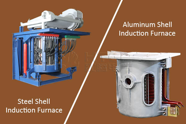
The body structure of a power-frequency induction furnace consists of several major components, including the furnace cover, furnace frame, furnace body, tilting mechanism, and the water/electricity input system. Among these, the furnace body itself contains the critical elements that directly influence melting performance and operational reliability.
This document provides a detailed technical overview of each structural component to support engineers and operational technicians in understanding the mechanical and electromagnetic design of a power-frequency induction furnace.
1. Furnace Body Structure
The furnace body is composed of the induction coil, crucible, magnetic yoke, and steel structural frame. Among these, the induction coil and magnetic yoke are the most critical for energy transfer and thermal efficiency.
1.1 Induction Coil Design
The induction coil of a power-frequency induction furnace is manufactured from high-conductivity copper tubing. While similar in principle to the coils used in medium-frequency and high-frequency furnaces, the power-frequency coil has several unique design characteristics:
1.1.1 Eccentric Tube Construction
The coil is made from a non-symmetrical, eccentric copper tube. This structural choice reduces deformation caused by electromagnetic forces, commonly known as the “hump phenomenon.”
By lowering the height of the hump, the furnace maintains a more stable molten bath shape during operation.
1.1.2 Coil Positioning
To minimize electromagnetic distortion:
-
The top of the coil is positioned below the molten bath hump
-
The bottom of the coil extends 1 to 2 turns below the crucible base
This arrangement helps maintain consistent electromagnetic stirring and stable furnace behavior during melting.
1.1.3 Mechanical Fixation
The coil is securely fixed to the steel frame through insulated pillars.
This is essential, because high current produces strong electromagnetic forces that may cause displacement or vibration if the coil is not rigidly supported.
1.2 Magnetic Yoke Structure
The magnetic yoke is built from layered silicon steel sheets forming a robust magnetic core surrounding the induction coil.
Functions of the Magnetic Yoke
1. Magnetic Flux Control
One primary function is to prevent magnetic flux leakage.
By concentrating magnetic lines around the coil, the yoke significantly enhances heating efficiency.
2. Structural Protection and Heat Reduction
Without a yoke, stray magnetic lines would induce eddy currents in the steel furnace frame, generating unwanted heat.
The yoke acts as a magnetic shield, eliminating this risk and allowing the frame to be positioned closer to the coil, resulting in:
-
A more compact furnace
-
Simplified structural design
Otherwise, the frame would need:
-
Non-magnetic materials
-
Greater distance from the coil
-
Or slotted magnetic isolation structures
All of which increase cost and complexity.
3. Coil Reinforcement
The yoke also mechanically strengthens the coil assembly.
It is secured axially and radially using spring-mounted bolts connected to the furnace shell and base.
The springs absorb vibration caused by dynamic electromagnetic forces during melting.
2. Hydraulic Transmission System
The body of a power-frequency induction furnace is mounted on a movable support.
Tilting the furnace for pouring is achieved through hydraulic plungers installed on both sides of the furnace frame.
The system allows a maximum tilt angle of 95 degrees for safe and efficient metal discharge.
The furnace cover also uses hydraulic actuation for opening, closing, and horizontal movement.
Both furnace tilting and cover movement share a single hydraulic system controlled by directional valves.
2.1 Components of the Hydraulic System
The system consists of:
-
Hydraulic oil tank
-
Hydraulic cylinders
-
High-pressure oil pump
-
Pump motor
-
Hydraulic valves
-
Operator control box
Furnace Tilting Cylinder
This cylinder is mounted between the fixed frame and movable support structure.
A limit switch prevents over-tilting when the furnace reaches its maximum 95-degree discharge position.
Furnace Cover Cylinder
Most cover cylinders are piston-type designs.
Fixed between the movable support and the cover, the cylinder controls:
-
Opening
-
Closing
-
Left/right rotation
This allows flexible access for charging materials and for maintaining furnace components.