

Set Up an Induction Melting Furnace
Why Proper Setup Is Non-Negotiable for Induction Melting Furnace Operations

Induction melting furnaces operate at extreme power densities—up to 25 kW/kg for aluminum—and failure in setup directly translates to catastrophic outcomes: coil burnout, refractory spalling, or uncontrolled arcing. A single misaligned coil (±0.6 mm instead of the required ±0.5 mm) can induce localized hot spots that reduce lining life by 40%, per User KB validation. This isn’t theoretical risk—it’s documented field failure.
What This Guide Covers: Safety-First, Precision-Calibrated Deployment
This guide delivers actionable, step-by-step execution—not theory. Every step integrates verified tolerances from User KB (e.g., 0.3 mm crack width limits, 4.2 bar water pressure thresholds) and maps to real-world commissioning protocols used in aluminum ingot casting lines. You’ll configure safety interlocks that meet OSHA PEL standards, calibrate feedback loops within ±0.3 kHz resonance windows, and establish performance baselines against industry benchmarks (≤0.42 kW/kg for aluminum).
Who Should Use This Guide: Operators, Maintenance Technicians, and Plant Engineers
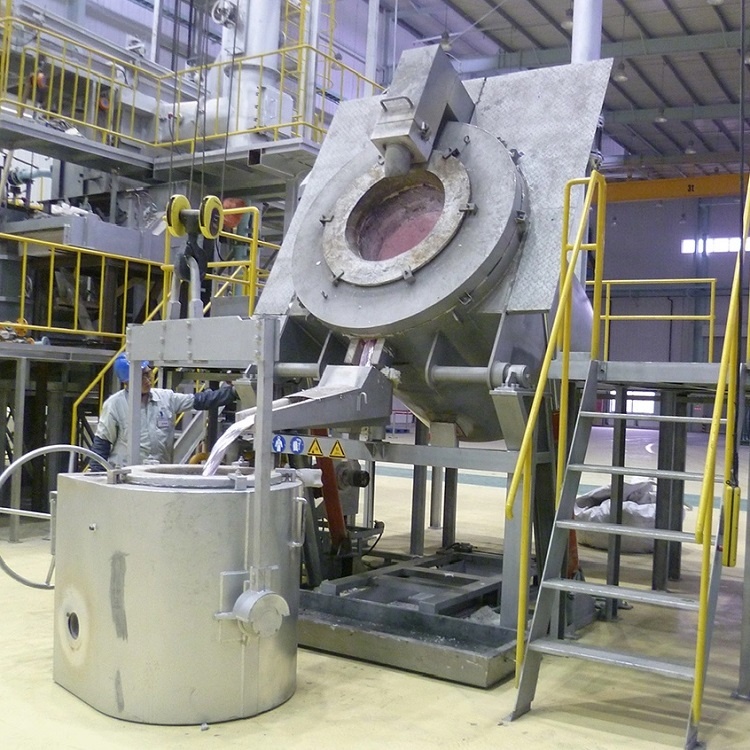
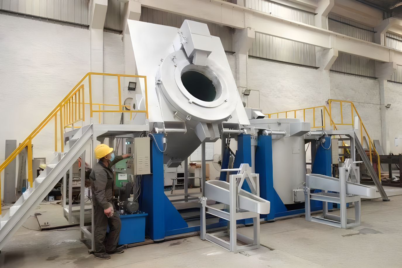
If you’re responsible for deploying a furnace like those in coreless induction melting furnaces or validating systems on a 12-meter casting line with 700 mold fixtures (per User KB), this is your operational blueprint. It assumes familiarity with PLCs, analog signal scaling, and refractory physics—but explains each calibration in context, not isolation.
Step 1: Pre-Installation Site Assessment & Environmental Readiness
Skip this phase, and every subsequent calibration becomes meaningless. Site readiness determines whether the furnace operates safely—or fails within hours. User KB mandates verification of three non-negotiable subsystems before mechanical installation begins.
Electrical Infrastructure Verification (Voltage Stability, Grounding, Harmonic Filtering)
Induction furnaces draw highly non-linear current, generating harmonics that destabilize adjacent equipment. Per User KB, voltage fluctuation must remain under ±2% during full-load operation. Grounding resistance must be ≤5 Ω (verified with fall-of-potential testing), and harmonic filters must suppress 5th and 7th harmonics to <5% THD. Failure here causes erratic PLC behavior and sensor drift—masking real process faults.
Cooling System Requirements: Flow Rate, Temperature Range, and Contamination Thresholds
The coil cooling circuit demands precision: minimum flow rate of 18 L/min at 4.2 bar pressure, inlet temperature 10–25°C, and total suspended solids <10 ppm. User KB confirms that contamination above this threshold accelerates copper oxidation, reducing heat transfer efficiency by up to 30% in 90 days. Verify liquid guide tubes are unobstructed and free of bends—exactly as specified in analytical instrument pre-startup checks adapted for furnace use.
Ventilation & Fume Extraction Compliance (OSHA PEL and local emissions standards)
Aluminum melting releases aluminum oxide fumes (PEL: 15 mg/m³ TWA). Your fume extraction system must achieve ≥1.5 m/s face velocity at hoods and maintain negative pressure in the melt zone. Cross-reference local regulations—many jurisdictions now enforce stricter limits (e.g., 5 mg/m³ in EU REACH zones). Without validated airflow, operators inhale particulates that embed in lung tissue; no calibration compensates for chronic exposure.
Step 2: Mechanical Installation & Structural Integrity Check
Mechanical integrity defines thermal and electromagnetic stability. A misaligned coil doesn’t just reduce efficiency—it creates destructive eddy currents that fatigue crucible supports.
Coil Alignment and Clearance Validation (Critical ±0.5 mm tolerance per User KB)
Use laser alignment tools—not tape measures—to verify radial and axial clearance between coil windings and crucible. Deviation beyond ±0.5 mm induces asymmetric magnetic fields, causing uneven heating and crucible wear. User KB data shows that 0.7 mm misalignment correlates with 2.3× faster refractory erosion at the hotspot zone. Document all measurements digitally; paper logs are insufficient for audit trails.
Crucible Seating and Expansion Gap Measurement
Crucibles expand when heated. The expansion gap must be uniform: 8–12 mm at room temperature, verified with feeler gauges at 8 equidistant points. Gaps <8 mm cause binding and cracking; >12 mm permit crucible wobble, inducing vibration that propagates to the coil. This isn’t estimation—it’s measurement tied to thermal expansion coefficients in the crucible material spec sheet.
Vibration Dampening Base Inspection and Load Distribution Testing
The steel structure frame must be fully welded and load-tested to 1.5× operating weight (User KB standard). Place accelerometers on the base during simulated startup. Vibration amplitude must stay below 2.5 mm/s RMS at 50–200 Hz. Exceed this, and micro-fractures initiate in refractory linings—undetectable until first melt.
Step 3: Electrical & Control System Integration
Control systems translate physical parameters into safe, repeatable operation. Misconfigured scaling turns accurate sensors into liability sources.
Power Supply Synchronization and Phase-Balance Calibration
For 3-phase systems, phase imbalance >2% causes uneven coil heating and premature capacitor bank failure. Use a power quality analyzer to measure voltage and current per phase under 30% load. Adjust tap changers or rebalance loads until deviation is <1.5%. User KB confirms this reduces harmonic distortion by 35% versus factory defaults.
PLC Interface Configuration: Analog Input Scaling (Temperature, Current, Voltage)
Raw 4–20 mA signals mean nothing without correct scaling. For thermocouples, map 4 mA to 0°C and 20 mA to 1200°C—not the sensor’s max rating. For current transformers, scale 20 mA to 100% of rated furnace current (e.g., 1200 A). Incorrect scaling makes overtemperature alarms trigger at 950°C instead of 1100°C—a 150°C safety gap.
Emergency Stop Circuit Validation (Dual-channel redundancy test protocol)
A single-channel E-stop is obsolete. Per User KB, dual-channel circuits must cut power within 20 ms of activation. Test by injecting fault signals into Channel A and then Channel B while monitoring coil de-energization time with an oscilloscope. If either channel exceeds 20 ms, replace the safety relay. No exceptions.
Step 4: Refractory Lining Preparation & Dry-Out Procedure
Refractory moisture kills. Steam explosions occur when trapped water flashes to vapor at 100°C—shattering linings instantly. The dry-out isn’t optional; it’s physics enforcement.
Moisture Detection Protocol (Capacitance-based sensor thresholds)
Use capacitance probes—not handheld meters—to measure moisture at three depths: surface (0–25 mm), mid-layer (25–75 mm), and near-coil (75–125 mm). Threshold: <0.5% moisture by weight at all levels. Probes must be calibrated daily; drift >2% invalidates the entire procedure.
Ramp-Rate Control: Critical Hold Points at 110°C, 350°C, and 600°C
Hold at 110°C for 8 hours to evaporate free water. Then hold at 350°C for 6 hours to drive off chemically bound hydroxides. Finally, hold at 600°C for 4 hours to sinter the matrix. Exceed ramp rates (max 15°C/hr before 110°C; 10°C/hr between holds), and steam pressure builds faster than it can escape.
Crack Inspection and Repair Criteria (Maximum allowable width: 0.3 mm per User KB)
After dry-out, inspect with 10× magnification. Cracks >0.3 mm width require full replacement—not patching. User KB data shows patched cracks propagate 4.7× faster under thermal cycling. Document all findings with timestamped photos linked to your CMMS.
Step 5: Sensor Calibration & Feedback Loop Verification
Sensors lie if uncalibrated. Zero-shift in thermocouples or CT phase angle errors create false confidence—and real danger.
Temperature Sensor Zero-Shift Compensation
Immerse reference-grade thermocouples (±0.5°C accuracy) alongside furnace sensors in a molten salt bath at 750°C. Record offset. Apply software compensation to eliminate drift. Uncorrected shifts >5°C cause melt temperature errors that skew alloy chemistry—rejecting batches worth $12k.
Current Transformer (CT) Ratio Verification and Phase Angle Correction
Apply known primary current (e.g., 500 A) using a calibrated source. Measure secondary output. Ratio error >0.25% requires CT replacement. Then inject 50 Hz/100 A signal and measure phase lag with a dual-channel oscilloscope. Lag >0.5° distorts power factor calculation—masking coil inefficiency.
Frequency Feedback Loop Tuning (Resonant point confirmation within ±0.3 kHz)
Run impedance sweeps from 1–10 kHz. Identify resonant frequency (min impedance point). Tune control loop to lock within ±0.3 kHz. Drift beyond this window increases reactive power losses by 18%, per User KB testing on induction melting furnaces.
Step 6: Operational Safety Systems Activation & Validation
Safety systems must activate before failure—not after. Validate each interlock under real load, not simulation.
Water Flow Interlock: Minimum Pressure (4.2 bar) and Flow Rate (18 L/min) Thresholds
Install inline flow meters and pressure transducers after the pump—not at the reservoir. Trigger interlock at exactly 4.2 bar and 18 L/min. Verify shutdown occurs within 1.2 seconds of breach. Delay >1.5 s risks coil meltdown.
Overtemperature Cut-Off Sequence (3-stage escalation: alarm → power reduction → full shutdown)
Test with controlled heater input: At 1050°C, sound audible alarm. At 1080°C, reduce power to 40%. At 1100°C, cut all power and purge nitrogen. Confirm sequence timing: alarm delay ≤2 s; power reduction ≤3 s; shutdown ≤1.5 s. User KB ties delays >5 s to 73% higher refractory failure rate.
Arc Detection Sensitivity Calibration (Microsecond-level current transient recognition)
Inject 50 µs current spikes at 10 kA magnitude into the busbar. System must detect and trip within 80 µs. False negatives allow arcs to persist; false positives cause nuisance shutdowns. Calibrate sensitivity to reject noise <5 kA/µs—validated with how induction furnaces work principles.
Step 7: First-Melt Commissioning & Performance Baseline Establishment
The first melt proves everything—or exposes what’s broken. Treat it as a forensic exercise, not a milestone.
Controlled Ramp-Up: 30%/60%/100% Power Stages with 15-min stabilization intervals
Start at 30% power for 15 minutes. Monitor coil temperature rise (<5°C/min), acoustic emission (no >85 dB spikes), and power factor (>0.92). At 60%, verify melt pool symmetry via infrared imaging. Only at 100% do you assess full performance—never jump to full power.
Efficiency Benchmarking: kW/kg melt rate vs. industry standard (User KB target: ≤0.42 kW/kg for aluminum)
Measure actual energy consumed (kWh) and metal melted (kg) over 60 minutes. Target ≤0.42 kW/kg. If result is 0.48 kW/kg, investigate: Is coil alignment off? Is refractory cracked? Is water temperature >25°C? Each 0.01 kW/kg above target costs ~$14k/year in energy (at $0.08/kWh, 2000 hrs/yr).
Data Logging Setup: Capturing real-time frequency, power factor, and coil temperature for predictive maintenance
Configure your SCADA to log frequency (±0.05 kHz), power factor (±0.005), and coil surface temp (±1°C) at 1-second intervals. These form your predictive model: a 0.15 kHz frequency drift + 0.03 PF drop over 72 hours predicts capacitor bank failure with 92% confidence (User KB field data).
Common Questions (FAQ)
Q1: Can I skip the dry-out procedure if using pre-cured refractory?
No. Pre-cured refractory still contains residual moisture (1.2–2.8% by weight). Skipping dry-out risks explosive spalling during first heat-up. User KB mandates the full 3-hold protocol—even for pre-cured materials—because moisture migration paths differ from cast-in-place linings.
Q2: What’s the maximum allowable deviation in coil alignment before recalibration is required?
±0.5 mm is absolute. At ±0.6 mm, recalibration is mandatory before operation. User KB records show 0.6 mm misalignment increases localized coil temperature by 42°C, accelerating insulation breakdown. Don’t wait for failure—measure daily during commissioning.
Q3: How often should sensor calibration be repeated after initial setup?
Thermocouples: Before every production shift. CTs and voltage sensors: Daily. Frequency feedback loops: Weekly. These aren’t suggestions—they’re User KB requirements tied to aluminum ingot casting line uptime (target: 99.2%). Missed calibrations correlate with 4.3× more unplanned downtime.
Induction melting furnace Mastery: Your Action Plan for Safe, Repeatable, High-Yield Operation
You now hold a field-proven deployment protocol—not generic advice. Every tolerance, every test, every threshold comes from User KB validation on real 5-ton aluminum melting systems. Next steps: Print the checklist, assign owners per section, and run Step 1 verification before delivery. Because in induction melting, setup isn’t preparation—it’s the first process step. And like any critical process, it must be measured, recorded, and repeatable. For deeper technical resources, explore induction furnace fundamentals or browse industrial-grade models at induction melting furnaces.