

Temperature Controller for Industrial Furnaces
Temperature Controller for Industrial Furnaces: Thermocouples and Pyrometers
A furnace temperature controller requires a measuring instrument that responds reliably to changes in temperature. Several physical effects can be used for this purpose: the expansion of solids, liquids or gases; changes in electrical resistance; and the electromotive force generated by two dissimilar conductors joined at a measuring junction.
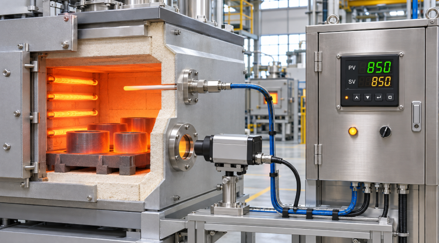
The radiation pyrometer described in the source also uses thermocouple elements, although these elements remain outside the furnace.
Temperature Measurement Principles
Each of these effects has been used for temperature measurement and control. The expansion of a solid, as employed in a bimetallic strip, is widely used for room-temperature control. Other effects have been incorporated into instruments suited to different furnace temperature ranges.
Electronic amplification made small electrical signals easier to measure and increased the importance of two temperature-dependent effects in furnace instrumentation: changes in electrical resistance and changes in thermocouple electromotive force.
These measurement methods were used before the discovery of the electron, and instruments based on them can operate without electronic amplification. Electronic instruments subsequently extended their measuring capabilities, particularly at low temperatures where the available signals are small.
Thermocouples for Furnace Temperature Control
The furnace control systems discussed in the source rely primarily on thermocouples.
A thermocouple consists of two wires made from different metals or alloys. The wires are joined at the hot, or measuring, junction. Their reference ends connect to a measuring instrument, such as a galvanometer or potentiometer. Thermocouples are generally supplied as part of the temperature-control equipment rather than fabricated by the user.
For the same measuring- and reference-junction temperatures, the electromotive force produced depends on the conductor materials.
Iron and constantan, a copper–nickel alloy, provide a comparatively large signal at lower temperatures. The source gives an upper measuring temperature of 650°C for this combination.
Chromel, a nickel–chromium alloy, and Alumel, a nickel–aluminum alloy, can be used up to 1,090°C according to the source. Higher temperatures may be possible with suitable protection.
Platinum–rhodium/platinum thermocouples are used for the higher industrial furnace temperatures discussed in the text.
Thermocouple Protection and Thermal Lag
Furnace gases, including oxygen, carbon monoxide and sulfur compounds, can corrode or embrittle thermocouple materials. The sensing elements are therefore enclosed in protective tubes.
One arrangement described in the source uses two concentric tubes: an inner metal tube and an outer ceramic tube.
Protection introduces a measurement consideration. Whenever the furnace temperature is changing, the temperature inside the protective tube does not exactly match the surrounding furnace temperature. This difference must be considered when interpreting the temperature controller’s indication during heating or cooling.
Radiation Pyrometers
Furnace temperature can also be measured without placing the thermocouple elements inside the furnace.
In the radiation pyrometer described here, several thermocouples are connected to form a thermopile. A clean lens focuses radiation from a hot target onto the thermopile’s measuring junctions, producing an electrical signal.
The target may be the closed end of a refractory tube exposed to the furnace temperature, or it may be the material being heated. These two measuring arrangements require different calibrations.
Original Figure 106: Operating principle of a radiation pyrometer. Diagram labels: target, lens, thermopile, compensation leads and indicating instrument.
The thermopile signal can also be used for automatic furnace temperature control. In the balancing arrangement described in the source, a force derived from the temperature-dependent signal is balanced against a preset force.
Galvanometers and Millivolt Indicators
Small thermoelectric signals were originally measured using suspended-coil galvanometers. These instruments were delicate and easily damaged.
A more robust instrument used jeweled bearings and was known as a millivoltmeter. In both designs, a hairspring balanced the torque produced by the electrical signal, allowing the pointer to indicate temperature.
For furnace control, this pointer movement could also initiate a control action. However, the pointer produced only a very small force, so its movement had to operate a relay or servomotor rather than directly control the heating equipment.
Direct-Contact Temperature Controllers
Electrical contacts provided a means of converting pointer movement into a control signal. Figure 107 illustrates this arrangement.
Contact arcing could damage the contacts, so the instrument had to operate through a low-current control circuit.
Original Figure 107: Simplified direct-contact temperature controller. 1: spring contact; 2: pyrometer; 3: heat-reduction relay; 4: heat-increase relay.
Depressor-Bar Temperature Controllers
The depressor-bar instrument shown in Figure 108 was a further development of the direct-contact design. It allowed stronger, more reliable contacts to be used.
The galvanometer pointer, identified as component 1, moved freely in a horizontal plane. At regular intervals, a depressor bar pushed the pointer downward.
If the pointer was within the deadband, or non-contact region, no control action occurred. If it was positioned above either leaf spring, identified as component 2, the downward movement closed the corresponding pair of insulated contacts. The resulting relay action either supplied heat to the furnace or stopped the heat input.
Although this arrangement improved on the direct-contact instrument, deterioration of the contacts remained a problem.
Original Figure 108: Simplified depressor-bar temperature controller. 1: galvanometer pointer; 2: leaf springs; 3: depressor bar; 4: heat-reduction relay; 5: heat-increase relay.