
Vacuum Induction Melting Furnaces
Vacuum Induction Melting Furnaces: Components, Structure & Power Supply
Vacuum induction melting (VIM) systems are highly specialized metallurgical installations engineered for advanced refining, casting, and alloy fabrication. Since the 1960s, VIM technologies have played an essential role in high-precision metallurgy, mechanical component manufacturing, and specialized aerospace materials production.
1. Core System Configuration of VIM Furnaces
An industrial vacuum induction melting installation relies on four main subsystems working together to maintain strict atmospheric controls and high thermal melting capacities:
-
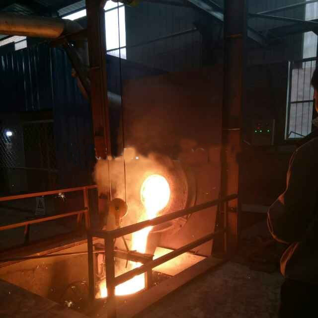
Furnace Body (Vessel Assembly): The structural vacuum chamber housing the primary crucible and induction assemblies.
-
Power & Electrical Control Network: Contains the medium-frequency power supply units, capacitor banks, and regulatory electrical cabinets.
-
Vacuum Pumping System: A series of heavy-duty mechanical, roots, or diffusion pumps designed to evacuate the chamber and remove atmospheric impurities.
-
Water Cooling Loop: High-pressure water lines that safely cool the induction coils, chamber walls, and power feeds.
2. Specialized Power Supply Engineering Requirements
The power configuration of a vacuum induction furnace is similar to a standard medium-frequency induction unit, typically utilizing medium-frequency generator sets, thyristor static inverters, or frequency multipliers. However, operating inside a vacuum introduces strict electrical constraints to ensure safe, stable operation:
A. Low Low-Terminal Inductor Voltage
The operational voltage across the induction heating coil must be kept much lower than in atmospheric furnaces, typically under 750V.
Critical Safety Mechanism: Under vacuum environments, the breakdown voltage of gases decreases significantly. If voltages exceed this threshold, it triggers gaseous glow discharges that can destroy the electrical insulation and cause catastrophic system failure.
B. Prevention of High-Order Harmonics
When using modern thyristor static inverter power supplies, high-order harmonics frequently feedback into the load circuit. This causes voltage spikes between the induction coil and the grounded furnace shell, increasing the risk of arcing.
To prevent this, engineers implement two primary modifications:
-
Medium-Frequency Isolation Transformers: Installed at the power output terminals to block incoming harmonic currents.
-
Dual-Coil Filter Reactors: Placed before the inverter section and wired in series with the positive and negative rectifier outputs to balance voltages relative to the furnace ground shell.
C. High Resonant Circuit Currents
Because these systems use low operating voltages, they require significantly higher electrical currents to meet the furnace’s power demands. This high current increases energy losses within the tank circuit. To reduce these power losses, the capacitor cabinets must be placed as close to the furnace body as possible.
3. Structural Classifications & Mechanical Layout
The main furnace body consists of five primary assemblies: the outer shell, internal induction coils, crucible refractory, mechanical tilting mechanisms, and water-cooled power lines.
Based on operational requirements, these systems are categorized by their tilting mechanics and enclosure configurations:
Mechanical Pouring Configurations
-
Rotating Crucible Design (Crucible-Tilt): The induction coil and crucible assembly tilt forward as a single unit inside the vacuum chamber to pour molten metal into a mold. This approach offers excellent pouring stream control and is a standard design for precision industrial production.
-
Tilting Furnace Assembly (Furnace-Tilt): The entire vacuum chamber tilts along with the crucible to complete the pour.
Enclosure Orientation & Layout
Industrial VIM units are manufactured in either horizontal or vertical profiles, depending on floor space and production needs:
| Enclosure Type | Structural Advantages | Optimal Processing Mode | Typical Industrial Applications |
| Horizontal Shell | Easy access to the internal crucible; straightforward cleaning, inspection, and maintenance. | Intermittent / Batch Processing. | Multi-alloy casting operations requiring frequent crucible access. |
| Vertical Shell | Small footprint; efficient vertical loading profiles. | Semi-Continuous Operations. | High-volume production lines where clean floor space is limited. |
4. Operational Duty Cycles: Batch vs. Semi-Continuous
The operating mode of a VIM system is selected based on production volume and target ingot sizes:
-
Batch (Intermittent) Processing: Best for lower-volume operations, typically with capacities under 200 kg. The system must be repressurized and opened between heats to harvest the casting and reload raw material.
-
Semi-Continuous Processing: Used for high-volume manufacturing, generally spanning capacities from 500 kg to 1,500 kg. These systems use vacuum airlocks and isolated charging chambers to introduce fresh metal and extract