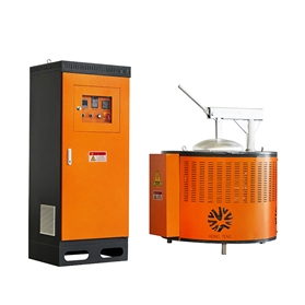
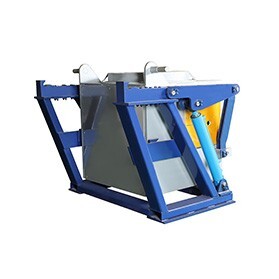
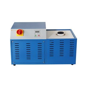
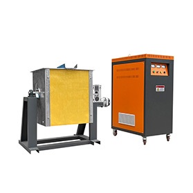
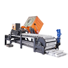
Luoyang HongtengIntermediate frequency induction furnace
Movable Furnace Covers, Pit Furnaces and Bogie Hearth Furnaces Structural Requirements for Movable Refractory Furnace Covers The force that the framework of a refractory brick furnace cover must withstand can be determined according to the principles used for arch roof design. The horizontal thrust, which can be calculated by multiplying the arch roof weight by the corresponding coefficient, not only produces tensile force but also tends to bend the metal framework. To resist these forces, the metal framework of a movable arch roof must be made very strong. A solid arch structure is often used for movable furnace covers on large pit-type annealing furnaces. This type of furnace cover has several features: each section is designed so that it can be pushed onto the top of another section; another feature is that one silica brick is inserted between every four fireclay bricks, which almost completely eliminates the overall expansion and contraction of the brickwork. The heating and cooling of this furnace cover have never been fast enough to damage the silica bricks. When designing a movable arch roof, convenient lifting and handling must also be considered. For this purpose, lifting holes are usually provided so that the hooks of the...
Vacuum Induction Furnace Architecture: Shell Engineering, Coaxial Power Feeds, and Vacuum Systems Vacuum induction melting (VIM) furnaces require precise integration of robust mechanical structures and complex electrical networks. Every aspect of the furnace body—from the structural steel shell to the vacuum-sealed dynamic electrodes—must handle massive pressure differentials and intense electromagnetic fields while maintaining a clean, airtight refining environment. 1. Furnace Shell Design & Structural Engineering The furnace body and its auxiliary assemblies comprise the core structural environment needed for charging, ramming, melting, and casting. Atmospheric Pressure Requirements Because the entire metallurgical process occurs inside the sealed chamber, the furnace shell must withstand immense compressive forces created by the deep internal vacuum. Ensuring high structural strength is a primary engineering priority. Shell Wall Configurations Industrial design variations balance thermal management with furnace capacity: Small-Scale Furnaces: These systems utilize a full double-walled structure across the entire vessel. The outer layer is welded from standard carbon steel plate, while the inner layer uses non-magnetic austenitic stainless steel to prevent stray induction heating. High-velocity cooling water flows continuously between these layers. Large-Scale Furnaces: To optimize manufacturing costs and structural efficiency, large installations use a single-walled steel plate layout as the baseline. Double-walled cooling jackets...
Vacuum Induction Melting Furnaces: Components, Structure & Power Supply Vacuum induction melting (VIM) systems are highly specialized metallurgical installations engineered for advanced refining, casting, and alloy fabrication. Since the 1960s, VIM technologies have played an essential role in high-precision metallurgy, mechanical component manufacturing, and specialized aerospace materials production. 1. Core System Configuration of VIM Furnaces An industrial vacuum induction melting installation relies on four main subsystems working together to maintain strict atmospheric controls and high thermal melting capacities: Furnace Body (Vessel Assembly): The structural vacuum chamber housing the primary crucible and induction assemblies. Power & Electrical Control Network: Contains the medium-frequency power supply units, capacitor banks, and regulatory electrical cabinets. Vacuum Pumping System: A series of heavy-duty mechanical, roots, or diffusion pumps designed to evacuate the chamber and remove atmospheric impurities. Water Cooling Loop: High-pressure water lines that safely cool the induction coils, chamber walls, and power feeds. 2. Specialized Power Supply Engineering Requirements The power configuration of a vacuum induction furnace is similar to a standard medium-frequency induction unit, typically utilizing medium-frequency generator sets, thyristor static inverters, or frequency multipliers. However, operating inside a vacuum introduces strict electrical constraints to ensure safe, stable operation: A. Low Low-Terminal Inductor Voltage...
Aluminum Tapping Operations: Thermodynamics, Logistics, and Field Safety In electrolytic reduction facilities, aluminum tapping is a highly regulated metallurgical procedure. Beyond basic siphoning, executing a tap requires a strict understanding of thermodynamics, mathematical plant logistics, and rigid dynamic field protocols to maximize product purity and maintain zero-accident metrics. 1. The Thermodynamic Necessity of Ladle Preheating Q49: Why must an aluminum tapping ladle be thoroughly preheated before extraction? A: If an empty tapping ladle remains exposed to the atmosphere for an extended period, its internal refractory lining absorbs ambient moisture. Introducing superheated molten aluminum directly into a cold, un-preheated ladle triggers severe thermodynamic reactions: Explosive Flash Moisture Expansion: The sudden contact with high-temperature liquid metal causes the trapped moisture within the lining to instantaneously flash into steam. This rapid volumetric expansion can cause violent molten metal splashing or catastrophic steam explosions, threatening field personnel and equipment. Chemical Contamination ($Al_2O_3$ and Hydrogen Enrichment): At elevated temperatures, the liquid aluminum reacts chemically with the trapped moisture ($\text{H}_2\text{O}$), generating hydrogen gas ($\text{H}_2$) and aluminum oxide ($\text{Al}_2\text{O}_3$). The hydrogen is rapidly absorbed into the liquid matrix, while the oxides form dense inclusions. This de-refines the aluminum, reducing its final chemical purity and complicating downstream holding...
Radiation Heat Exchangers When a small flame or high-temperature exhaust stream flows along the center of a large conduit, the pipe walls receive only a limited amount of radiant heat per unit area. By applying this specific thermodynamic principle, engineers can design and manufacture highly robust and durable metal radiation heat exchangers (recuperators) for industrial applications. 1. Core Design and Structural Mechanics The Basic Radiation Recuperator Configuration The simplest form of an early-stage radiation heat exchanger used for forging furnaces consists of concentric cylinders: Exhaust Flow: Waste flue gas enters the recuperator via an opening located on the furnace roof. The diameter of this opening is typically smaller than the diameter of the heat exchanger’s outer shell. Gas Mixing & Passage: Inside the inner shell, the hot gas column gradually mixes with the surrounding cooler gases. Concurrently, air passes at high velocity through the narrow annular channel configured between the inner and outer shells. Insulation: The outer shell of the heat exchanger is completely insulated to minimize ambient thermal losses. Managing Differential Thermal Expansion If the diameter of the roof opening is larger than the furnace top opening, and the air passage remains narrow, the differential thermal expansion between the...
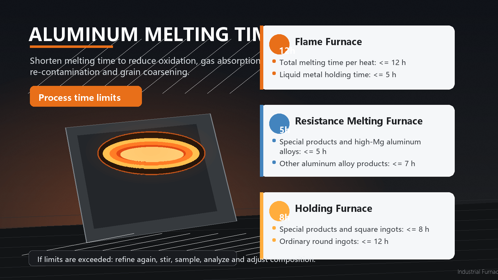
How Long Should Melting Time Be Controlled? Melting time refers to the total time from the start of charging and heating the furnace charge to the discharge of the melt from the furnace. It is the total time that the charge remains in the melting furnace in solid and liquid forms. The longer the melting time, the more serious the oxidation and gas absorption of the charge, especially the liquid aluminum melt. The tendency of ingots to form coarse crystal structures and cracks also increases. At the same time, the productivity of the melting furnace decreases. For the refined melt, the longer it stays in the furnace, the greater the possibility of re-contamination, composition change, and failure of grain refinement treatment. Therefore, under the premise of ensuring the time required to complete a series of process operations, the melting time should be shortened as much as possible. According to production practice in aluminum processing plants, the allowable holding time varies in different furnaces. The general requirements are as follows: 1. Flame Furnace For each heat, the total melting time must not exceed 12 hours, and the holding time of liquid metal must not exceed 5 hours. 2. Resistance Melting Furnace The time...
Induction Steel Melting Furnace
Aluminum Induction Melting Furnace
Stainless Steel Induction Melting Furnace
Medium Frequency Gold Induction Melting Furnace
Small Medium Frequency Induction Furnace
Aluminum/Copper Ingot Continuous Casting Line
Please fill out the form below (required *), send us a short message, and we will contact you as soon as possible.
Send Message
Copyright © 2026 Luoyang Hongteng Electrical Equipment Co., Ltd.